Install the app
How to install the app on iOS
Follow along with the video below to see how to install our site as a web app on your home screen.
Nota: This feature may not be available in some browsers.
Je gebruikt een verouderde webbrowser. Het kan mogelijk deze of andere websites niet correct weergeven.
Het is raadzaam om je webbrowser te upgraden of een alternatieve webbrowser te gebruiken.
Het is raadzaam om je webbrowser te upgraden of een alternatieve webbrowser te gebruiken.
7 cilinder 120 cc radiaal motor
- Topicstarter pat1311
- Startdatum
Wat dacht je dan dat een RCexl was.....dat is gewoon een soort Arduino, maar dan in PIC vorm.
Reset magneetje zit een x aantal graden voor de eerste cilinder en reset de counter (tav nu komt de eerste cilinder).
De gewone magneetjes vertellen de PIC wanneer hij weer moet ontsteken voor de volgende cilinder.
Alleen bij een advange CDI zal het signaal van de gasservo ook een rol spelen want dan komt er vervroeging of verlaten bij van de puls.
Ik snap dat er in een RcExl (of CH) een processor zit, en dat dat vergelijkbaar is met een Arduino of een PIC, maar dat zijn alle processors, Arduino's en PIC's.
Wat ik bedoel te zeggen is dat je van de code in whatever er in zo'n automatische on-board glow zit, niks kunt gebruiken voor een CDI aan te sturen omdat glow en CDI twee heel verschillende dingen zijn.
En als je de code wist/vervangt, is het niet meer hetzelfde ding, slechts het blokje waar het in zit is nog hetzelfde.
Hoezo? RcExl heeft ook een vervroeging, en die heeft geen verbinding met de gasservo of de gasklep.... Dat zoekt dat ding helemaal zelfstandig uit.Alleen bij een advange CDI zal het signaal van de gasservo ook een rol spelen want dan komt er vervroeging of verlaten bij van de puls.
Dat is een vaste curve en voor iedere 1 cilinder of 2 cilinder inline of 180 graden motor gelijk.
Helaas is niet iedere motor gelijk en als je de motor optimaal wilt laten draaien zal je de curve moeten aanpassen aan de motor.
In de afgelopen 20 jaar zijn er al heel wat CDI's door mijn handen gegaan en haast wel voor elk type motor, van 1,5cc'tje modelmotortje tot race motoren.
Ik weet echt wel waar ik het over heb, lees RCuniverse of RCgroups maar eens na....beginnen bij het begin in ~1997")
Helaas is niet iedere motor gelijk en als je de motor optimaal wilt laten draaien zal je de curve moeten aanpassen aan de motor.
In de afgelopen 20 jaar zijn er al heel wat CDI's door mijn handen gegaan en haast wel voor elk type motor, van 1,5cc'tje modelmotortje tot race motoren.
Ik weet echt wel waar ik het over heb, lees RCuniverse of RCgroups maar eens na....beginnen bij het begin in ~1997
Maar ook daarvoor, heb je geen verbinding met je gasservo nodig....als je de motor optimaal wilt laten draaien zal je de curve moeten aanpassen aan de motor.
Dat beweer ik ook nergens Bert, zo zit dat bij de glowplug moduul die hier aangehaald werd.
http://philsradial.blogspot.nl/2013/02/glowplug-driver.html
http://philsradial.blogspot.nl/2013/02/glowplug-driver.html
Ik had de code nog niet bekeken maar idd,daar heb je niks aan voor een cdi,waar 't om gaat,het timen van de onsteking sequence en de goede volgorde en daar staat niks over in.
Maar je kunt natuurlijk wel een arduino gebruiken en zelf een sketch schrijven,jammer genoeg ben ik redelijk in code kopieren en lichtjes aanpassen maar dan houdt 't ook wel op.
Mischien heeft er wel al eens iemand zoiets gemaakt en kan ik dat gebruiken,maakt niet uit voor hoeveel cilinders,das makkelijk aan te passen,ik ga eens rond snuffelen
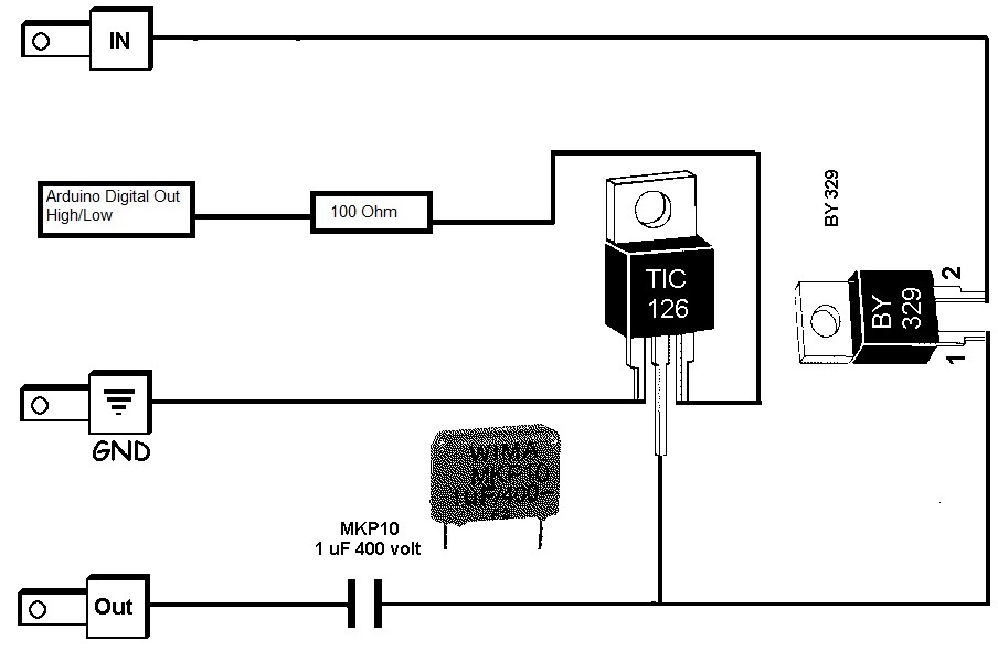
mischien zoiets maal 7?
En dan nog wat code natuurlijk
1
2
3
4
5
6
7
8
9
10
11
12
13
14
15
16
17
18
19
20
21
22
23
24
25
26
27
28
int ignitionpin = 8; // ignition trigger pin pulse output
volatile byte revolutions;
void setup()
{
Serial.begin(9600);
attachInterrupt(0, rpm_fun, RISING);
pinMode (ignitionpin, OUTPUT);
digitalWrite (ignitionpin, LOW);
revolutions = 0;
}
void loop()
{
if (revolutions >=1) {
delay(50);
digitalWrite (ignitionpin, HIGH);
delay(1);
digitalWrite (ignitionpin, LOW);
revolutions = 0;
}
}
void rpm_fun()
{
revolutions++;
}
Nog wat code jatten ergens voor de inputs van de hall sensor.
Je zou de delay aan het toerental kunnnen koppelen zodat je daarmee een vervroeging bereikt.
Dit moet toch allemaal goed te doen zijn.
http://video.illutron.dk/4465660/46...ideo_medium/spark-plug-from-arduino-video.mp4
Laatst bewerkt:
Nou,een quick search levert genoeg stof tot inspiratie op.
Wel weer een project an sich maar daar zijn we niet vies van")
hier iets compleet met vervroeging bij verschillende toerentallen,valt ook wel iets van te maken lijkt me zo.

#include <Avr/interrupt.h>
#include <Avr/io.h>
//Pin definitions:
const byte HallPin1 = 2; // Pin nr 2 to Hall sensor
const byte HallPin2 = 3; // Pin nr 3 is also to Hall sensor
const byte IgnOnPin = 4; // Ignition switch
const byte Ign1Pin = 8; // (PORTB,0)
const byte Ign2Pin = 12; // (PORTB,4)
volatile unsigned int cranktime; // Time from 3 degrees to where the coil should start to load.
volatile unsigned int crankingDwellTime; // The time the coil should charge during cranking
volatile long int microseconds; // The microsecondcounter value.
volatile long int half_revolution_time; // The time it takes for the crank to turn 1/2 revolution.
volatile int runningDwellTime; // The time the coil should charge during running
volatile int dwellTime; // The time the coil should charge.
volatile int IgnSystem; // Statusword for active ign system.
volatile byte IgnOn;
/***********************************************************************/
void setup() {
pinMode(Ign1Pin, OUTPUT); // Initialize the Ignition 1 pin as an output.
pinMode(Ign2Pin, OUTPUT); // -“-
pinMode(HallPin1, INPUT_PULLUP); // To get rid of RFI interference
pinMode(HallPin2, INPUT_PULLUP); // -“-
pinMode(IgnOnPin, INPUT_PULLUP); // -“-
bitClear(PORTB, 0); //digitalWrite(Ign2Pin, LOW); //Turn the ignition off in case it’s on
bitClear(PORTB, 4); //digitalWrite(Ign1Pin, LOW); // -“-
attachInterrupt(digitalPinToInterrupt(HallPin1), SensorOn, RISING); //Hall sensor DI for Ignition 1
attachInterrupt(digitalPinToInterrupt(HallPin2), SensorOff, FALLING); //-“- 2
crankingDwellTime = 4000; //in uS
runningDwellTime = 3000; //in uS
half_revolution_time = 0;
IgnSystem = 0; // No ignition system is active (cranking mode).
IgnOn=LOW;
IgnOn = digitalRead(IgnOnPin);
/********** Setup timer2*************/
noInterrupts();
TCCR2A = 0; // Turn off Control register for waveform generation
TCCR2B = 0; // Turn off noise cancelling, turn off edge select, waveform gen mode 0,
TCCR2A |= (1 << WGM21); // Turn on CTC mode (so it will start again) automatically
TIMSK2 |= (1 << OCIE2A); // Set interrupt on compare match.
OCR2A = 8; // Prescaler of 64 gives 4uS per tick, 4uS * 8 = 32uS (32uS = 1 degree at ~5100rpm).
TCNT2 = 0; // Reset timer counter to 0
microseconds = 0; // Preset the us counter variable.
interrupts();
}
//========================================================================
/* The interrupt action for magnet 1: The Timer starts to count up 32 uS at a time.
**********************/
void SensorOff () {
if (IgnOn == HIGH){
half_revolution_time = microseconds; // For engine speed measurement
TCNT2 = 0; // Reset the timer count to 0
microseconds = 0; // reset the uS counter variable
TCCR2B |= (1 << CS22); // Load 64 prescaler, and this starts the timer2!
// While cranking (rpm < 300), the coil nr 2 will start to charge at once.
if ((half_revolution_time>100000)||(half_revolution_time==0)) {
IgnSystem = 2;
bitSet(PORTB,4); //digitalWrite(Ign2Pin, HIGH); // (Turn on coil 2 charging immediately.)
dwellTime = crankingDwellTime; //Setting the dwelltime for cranking.
cranktime = 0; //Setting the cranktime to 0 for immediate coil charging.
}
// While running (rpm >= 300), coil nr 2 will be used at next ignition.
if ((half_revolution_time<=100000)&&(half_revolution_time!=0)){
IgnSystem = 1; //start using coil nr1 instead.
dwellTime = runningDwellTime; //setting the dwelltime for running
}
}
}
/*========================================================================
The interrupt action for magnet 2: The Timer starts to count up 32uS at a time.
********************************/
void SensorOn () {
if (IgnOn == HIGH){
half_revolution_time = microseconds; // For engine speed measurement
TCNT2 = 0; // Reset the timer count to 0
microseconds = 0; // reset the uS counter variable
TCCR2B |= (1 << CS22); // Load 64 prescaler, and this starts the timer2!
// While cranking (rpm < 300), the coil nr 1 will start to charge at once.
if ((half_revolution_time>100000)||(half_revolution_time==0)) {
IgnSystem = 1;
bitSet(PORTB,0); //digitalWrite(Ign1Pin, HIGH); // (Turn on coil 1 charging immediately,)
dwellTime = crankingDwellTime; //setting the dwelltime for cranking.
cranktime = 0; //Setting the cranktime to 0 for immediate coil charging.
}
// While running (rpm >= 300), coil nr 2 will be used at next ignition.
if ((half_revolution_time<=100000)&&(half_revolution_time!=0)){
IgnSystem = 2; //start using coil nr2 instead.
dwellTime = runningDwellTime; //setting the dwelltime for running
}
}
}
/*=============================================================================
The Interrupt Service Routine for Timer2 that will be executed each time the timer reach the compare match register (32uS)*/
ISR(TIMER2_COMPA_vect) {
microseconds=microseconds+32; // Increases the variable “microseconds” by 32 every time the ISR is executed).
/************ coil charging*****************************/
if ((microseconds >= cranktime) && (microseconds < (cranktime+dwellTime))) {
if (IgnSystem == 1) { //If ignitionsystem 1 is selected, then:
bitSet(PORTB,0); //(Turn on coil 1 charging.) //digitalWrite(Ign1Pin, HIGH);
} if (IgnSystem == 2) { //If ignitionsystem 2 is selected, then:
bitSet(PORTB,4); //(Turn on coil 2 charging.) //digitalWrite(Ign2Pin, HIGH);
}
}
/***********Discharge coilspark*******************************************/
// When the microseconds has reached the cranktime and dwelltime, then:
if (microseconds >=(cranktime + dwellTime)) {
bitClear(PORTB, 0); //digitalWrite(Ign1Pin, LOW); //( Stop charging coil 1. (Gives spark))
bitClear(PORTB, 4); // digitalWrite(Ign2Pin, LOW); // As above.
// _________________________________________________________________________________________________________
if (microseconds > 100000) { // If the engine has stopped or still cranking, stop and reset the timer.
TCCR2B &= ~(1 << CS22); // Clear the prescaler, and this stops the timer2!
TCCR2B = 0;
microseconds = 0;
}
}
}
/***********************************************************/
void loop() {
IgnOn = digitalRead(IgnOnPin); // Check the status of the ignition switch
// Ignition advance curve.
//Following numbers are based on a excell sheet with the advance curve attached.
if (half_revolution_time> 6208 ){ ///Advance 0 @ >4100 rpm (rev limitation)
cranktime=7195-dwellTime;}
if ((half_revolution_time<= 7500 ) && (half_revolution_time> 7317 )){ ///Advance 28 @ 4000-4100 rpm (rev limitation)
cranktime=6208-dwellTime;}
if ((half_revolution_time<= 9091 ) && (half_revolution_time> 7500 )){ ///Advance 28 @ 4000-3300 rpm
cranktime=7525-dwellTime;}
if ((half_revolution_time<= 10000 ) && (half_revolution_time> 9091 )){ ///Advance 27,5 @ 3300-3000 rpm
cranktime=8306-dwellTime;}
if ((half_revolution_time<= 10714 ) && (half_revolution_time> 10000 )){ ///Advance 27 @ 3000-2800 rpm
cranktime=8929-dwellTime;}
if ((half_revolution_time<= 11111 ) && (half_revolution_time> 10714 )){ ///Advance 26 @ 2800-2700 rpm
cranktime=9321-dwellTime;}
if ((half_revolution_time<= 12500 ) && (half_revolution_time> 11111 )){ ///Advance 24 @ 2700-2400 rpm
cranktime=10625-dwellTime;}
if ((half_revolution_time<= 15000 ) && (half_revolution_time> 12500 )){ ///Advance 22 @ 2400-2000 rpm
cranktime=12917-dwellTime;}
if ((half_revolution_time<= 15789 ) && (half_revolution_time> 15000 )){ ///Advance 20 @ 2000-1900 rpm
cranktime=13772-dwellTime;}
if ((half_revolution_time<= 16667 ) && (half_revolution_time> 15789 )){ ///Advance 18 1900-1800 rpm
cranktime=14722-dwellTime;}
if ((half_revolution_time<= 18750 ) && (half_revolution_time>= 16667 )){ //Advance 16 @ 1800-1600 rpm
cranktime=16771-dwellTime;}
if ((half_revolution_time<= 20000 ) && (half_revolution_time>= 18750 )){ //Advance 14 @ 1600-1500 rpm
cranktime=18111-dwellTime;}
if ((half_revolution_time<= 21429 ) && (half_revolution_time>=20000 )){ //Advance 12 @ 1500-1400 rpm
cranktime=19643-dwellTime;}
if ((half_revolution_time<=25000 ) && (half_revolution_time>= 21429 )){ //Advance 10 @ 1400-1200 rpm
cranktime=23194-dwellTime;}
if ((half_revolution_time<=27273 ) && (half_revolution_time>=25000 )){ //Advance 9 @ 1200-1100 rpm
cranktime=25455-dwellTime;}
if ((half_revolution_time<= 30000) && (half_revolution_time>=27273 )){ //Advance 8 @ 1100-1000 rpm
cranktime=28167-dwellTime;}
if ((half_revolution_time<= 33333) && (half_revolution_time>= 30000 )){ //Advance 7,5 @ 1000-900 rpm
cranktime=31389-dwellTime;}
if ((half_revolution_time<=42857 ) && (half_revolution_time>= 33333 )){ //Advance 7 @ 900-700 rpm
cranktime=40476-dwellTime;}
if ((half_revolution_time<=50000 ) && (half_revolution_time>= 42857)){ //Advance 7 @ 700-600 rpm
cranktime=47222-dwellTime;}
if ((half_revolution_time<= 75000 ) && (half_revolution_time>= 50000 )){ //Advance 9 @ 600-400 rpm
cranktime=70000-dwellTime;}
if ((half_revolution_time<= 85714) && (half_revolution_time>= 75000 )){ //Advance 2 @ 400-350 rpm
cranktime=83333-dwellTime;}
if ((half_revolution_time<= 100000 ) && (half_revolution_time>= 85714 )){ //Advance -2,5 @ 350-300 rpm
cranktime=99722-dwellTime;}
Wel weer een project an sich maar daar zijn we niet vies van
hier iets compleet met vervroeging bij verschillende toerentallen,valt ook wel iets van te maken lijkt me zo.
#include <Avr/interrupt.h>
#include <Avr/io.h>
//Pin definitions:
const byte HallPin1 = 2; // Pin nr 2 to Hall sensor
const byte HallPin2 = 3; // Pin nr 3 is also to Hall sensor
const byte IgnOnPin = 4; // Ignition switch
const byte Ign1Pin = 8; // (PORTB,0)
const byte Ign2Pin = 12; // (PORTB,4)
volatile unsigned int cranktime; // Time from 3 degrees to where the coil should start to load.
volatile unsigned int crankingDwellTime; // The time the coil should charge during cranking
volatile long int microseconds; // The microsecondcounter value.
volatile long int half_revolution_time; // The time it takes for the crank to turn 1/2 revolution.
volatile int runningDwellTime; // The time the coil should charge during running
volatile int dwellTime; // The time the coil should charge.
volatile int IgnSystem; // Statusword for active ign system.
volatile byte IgnOn;
/***********************************************************************/
void setup() {
pinMode(Ign1Pin, OUTPUT); // Initialize the Ignition 1 pin as an output.
pinMode(Ign2Pin, OUTPUT); // -“-
pinMode(HallPin1, INPUT_PULLUP); // To get rid of RFI interference
pinMode(HallPin2, INPUT_PULLUP); // -“-
pinMode(IgnOnPin, INPUT_PULLUP); // -“-
bitClear(PORTB, 0); //digitalWrite(Ign2Pin, LOW); //Turn the ignition off in case it’s on
bitClear(PORTB, 4); //digitalWrite(Ign1Pin, LOW); // -“-
attachInterrupt(digitalPinToInterrupt(HallPin1), SensorOn, RISING); //Hall sensor DI for Ignition 1
attachInterrupt(digitalPinToInterrupt(HallPin2), SensorOff, FALLING); //-“- 2
crankingDwellTime = 4000; //in uS
runningDwellTime = 3000; //in uS
half_revolution_time = 0;
IgnSystem = 0; // No ignition system is active (cranking mode).
IgnOn=LOW;
IgnOn = digitalRead(IgnOnPin);
/********** Setup timer2*************/
noInterrupts();
TCCR2A = 0; // Turn off Control register for waveform generation
TCCR2B = 0; // Turn off noise cancelling, turn off edge select, waveform gen mode 0,
TCCR2A |= (1 << WGM21); // Turn on CTC mode (so it will start again) automatically
TIMSK2 |= (1 << OCIE2A); // Set interrupt on compare match.
OCR2A = 8; // Prescaler of 64 gives 4uS per tick, 4uS * 8 = 32uS (32uS = 1 degree at ~5100rpm).
TCNT2 = 0; // Reset timer counter to 0
microseconds = 0; // Preset the us counter variable.
interrupts();
}
//========================================================================
/* The interrupt action for magnet 1: The Timer starts to count up 32 uS at a time.
**********************/
void SensorOff () {
if (IgnOn == HIGH){
half_revolution_time = microseconds; // For engine speed measurement
TCNT2 = 0; // Reset the timer count to 0
microseconds = 0; // reset the uS counter variable
TCCR2B |= (1 << CS22); // Load 64 prescaler, and this starts the timer2!
// While cranking (rpm < 300), the coil nr 2 will start to charge at once.
if ((half_revolution_time>100000)||(half_revolution_time==0)) {
IgnSystem = 2;
bitSet(PORTB,4); //digitalWrite(Ign2Pin, HIGH); // (Turn on coil 2 charging immediately.)
dwellTime = crankingDwellTime; //Setting the dwelltime for cranking.
cranktime = 0; //Setting the cranktime to 0 for immediate coil charging.
}
// While running (rpm >= 300), coil nr 2 will be used at next ignition.
if ((half_revolution_time<=100000)&&(half_revolution_time!=0)){
IgnSystem = 1; //start using coil nr1 instead.
dwellTime = runningDwellTime; //setting the dwelltime for running
}
}
}
/*========================================================================
The interrupt action for magnet 2: The Timer starts to count up 32uS at a time.
********************************/
void SensorOn () {
if (IgnOn == HIGH){
half_revolution_time = microseconds; // For engine speed measurement
TCNT2 = 0; // Reset the timer count to 0
microseconds = 0; // reset the uS counter variable
TCCR2B |= (1 << CS22); // Load 64 prescaler, and this starts the timer2!
// While cranking (rpm < 300), the coil nr 1 will start to charge at once.
if ((half_revolution_time>100000)||(half_revolution_time==0)) {
IgnSystem = 1;
bitSet(PORTB,0); //digitalWrite(Ign1Pin, HIGH); // (Turn on coil 1 charging immediately,)
dwellTime = crankingDwellTime; //setting the dwelltime for cranking.
cranktime = 0; //Setting the cranktime to 0 for immediate coil charging.
}
// While running (rpm >= 300), coil nr 2 will be used at next ignition.
if ((half_revolution_time<=100000)&&(half_revolution_time!=0)){
IgnSystem = 2; //start using coil nr2 instead.
dwellTime = runningDwellTime; //setting the dwelltime for running
}
}
}
/*=============================================================================
The Interrupt Service Routine for Timer2 that will be executed each time the timer reach the compare match register (32uS)*/
ISR(TIMER2_COMPA_vect) {
microseconds=microseconds+32; // Increases the variable “microseconds” by 32 every time the ISR is executed).
/************ coil charging*****************************/
if ((microseconds >= cranktime) && (microseconds < (cranktime+dwellTime))) {
if (IgnSystem == 1) { //If ignitionsystem 1 is selected, then:
bitSet(PORTB,0); //(Turn on coil 1 charging.) //digitalWrite(Ign1Pin, HIGH);
} if (IgnSystem == 2) { //If ignitionsystem 2 is selected, then:
bitSet(PORTB,4); //(Turn on coil 2 charging.) //digitalWrite(Ign2Pin, HIGH);
}
}
/***********Discharge coilspark*******************************************/
// When the microseconds has reached the cranktime and dwelltime, then:
if (microseconds >=(cranktime + dwellTime)) {
bitClear(PORTB, 0); //digitalWrite(Ign1Pin, LOW); //( Stop charging coil 1. (Gives spark))
bitClear(PORTB, 4); // digitalWrite(Ign2Pin, LOW); // As above.
// _________________________________________________________________________________________________________
if (microseconds > 100000) { // If the engine has stopped or still cranking, stop and reset the timer.
TCCR2B &= ~(1 << CS22); // Clear the prescaler, and this stops the timer2!
TCCR2B = 0;
microseconds = 0;
}
}
}
/***********************************************************/
void loop() {
IgnOn = digitalRead(IgnOnPin); // Check the status of the ignition switch
// Ignition advance curve.
//Following numbers are based on a excell sheet with the advance curve attached.
if (half_revolution_time> 6208 ){ ///Advance 0 @ >4100 rpm (rev limitation)
cranktime=7195-dwellTime;}
if ((half_revolution_time<= 7500 ) && (half_revolution_time> 7317 )){ ///Advance 28 @ 4000-4100 rpm (rev limitation)
cranktime=6208-dwellTime;}
if ((half_revolution_time<= 9091 ) && (half_revolution_time> 7500 )){ ///Advance 28 @ 4000-3300 rpm
cranktime=7525-dwellTime;}
if ((half_revolution_time<= 10000 ) && (half_revolution_time> 9091 )){ ///Advance 27,5 @ 3300-3000 rpm
cranktime=8306-dwellTime;}
if ((half_revolution_time<= 10714 ) && (half_revolution_time> 10000 )){ ///Advance 27 @ 3000-2800 rpm
cranktime=8929-dwellTime;}
if ((half_revolution_time<= 11111 ) && (half_revolution_time> 10714 )){ ///Advance 26 @ 2800-2700 rpm
cranktime=9321-dwellTime;}
if ((half_revolution_time<= 12500 ) && (half_revolution_time> 11111 )){ ///Advance 24 @ 2700-2400 rpm
cranktime=10625-dwellTime;}
if ((half_revolution_time<= 15000 ) && (half_revolution_time> 12500 )){ ///Advance 22 @ 2400-2000 rpm
cranktime=12917-dwellTime;}
if ((half_revolution_time<= 15789 ) && (half_revolution_time> 15000 )){ ///Advance 20 @ 2000-1900 rpm
cranktime=13772-dwellTime;}
if ((half_revolution_time<= 16667 ) && (half_revolution_time> 15789 )){ ///Advance 18 1900-1800 rpm
cranktime=14722-dwellTime;}
if ((half_revolution_time<= 18750 ) && (half_revolution_time>= 16667 )){ //Advance 16 @ 1800-1600 rpm
cranktime=16771-dwellTime;}
if ((half_revolution_time<= 20000 ) && (half_revolution_time>= 18750 )){ //Advance 14 @ 1600-1500 rpm
cranktime=18111-dwellTime;}
if ((half_revolution_time<= 21429 ) && (half_revolution_time>=20000 )){ //Advance 12 @ 1500-1400 rpm
cranktime=19643-dwellTime;}
if ((half_revolution_time<=25000 ) && (half_revolution_time>= 21429 )){ //Advance 10 @ 1400-1200 rpm
cranktime=23194-dwellTime;}
if ((half_revolution_time<=27273 ) && (half_revolution_time>=25000 )){ //Advance 9 @ 1200-1100 rpm
cranktime=25455-dwellTime;}
if ((half_revolution_time<= 30000) && (half_revolution_time>=27273 )){ //Advance 8 @ 1100-1000 rpm
cranktime=28167-dwellTime;}
if ((half_revolution_time<= 33333) && (half_revolution_time>= 30000 )){ //Advance 7,5 @ 1000-900 rpm
cranktime=31389-dwellTime;}
if ((half_revolution_time<=42857 ) && (half_revolution_time>= 33333 )){ //Advance 7 @ 900-700 rpm
cranktime=40476-dwellTime;}
if ((half_revolution_time<=50000 ) && (half_revolution_time>= 42857)){ //Advance 7 @ 700-600 rpm
cranktime=47222-dwellTime;}
if ((half_revolution_time<= 75000 ) && (half_revolution_time>= 50000 )){ //Advance 9 @ 600-400 rpm
cranktime=70000-dwellTime;}
if ((half_revolution_time<= 85714) && (half_revolution_time>= 75000 )){ //Advance 2 @ 400-350 rpm
cranktime=83333-dwellTime;}
if ((half_revolution_time<= 100000 ) && (half_revolution_time>= 85714 )){ //Advance -2,5 @ 350-300 rpm
cranktime=99722-dwellTime;}
Laatst bewerkt:

Laatst bewerkt:
Ik heb niet veel tijd gehad de laatste weken,veel overwerken dus veel mijn werk en weinig in mijn garage.
Toch wat zinnigs kunnen doen.
De laatste nokkenschijf die ik gemaakt had was ik toch niet helemaal tevreden over en heb 'm dus opnieuw gemaakt(voor de 6de keer dus...)
De nokvorm klopte niet helemaal met de tekening,de flanken waren iets te steil,zal wel te maken hebben met de radius van mijn frees en de manier waarop ik mijn diagram had gemaakt.
ook was mijn binnentandwiel binnen uit Duitsland en dat is dus echt te duur om te verkloten,moest dus deze keer echt 100 punten worden.
En dat is uiteindelijk gelukt.

Dik tandwiel,C45 afgedraaid tot 5 mm dikte.
Hier nr. 5 en het halffabrikaat van 6a en 6b..


En in de motor..

Mechanisch is de distributie in het carter nu helemaal klaar en binnen 0,02 mm precies,hier kan het iig niet meer aan liggen.
Ook mijn zelfgemaakte tandwieltjes doen 't perfect,ik ben blij en tevreden .
.
Toch wat zinnigs kunnen doen.
De laatste nokkenschijf die ik gemaakt had was ik toch niet helemaal tevreden over en heb 'm dus opnieuw gemaakt(voor de 6de keer dus...)
De nokvorm klopte niet helemaal met de tekening,de flanken waren iets te steil,zal wel te maken hebben met de radius van mijn frees en de manier waarop ik mijn diagram had gemaakt.
ook was mijn binnentandwiel binnen uit Duitsland en dat is dus echt te duur om te verkloten,moest dus deze keer echt 100 punten worden.
En dat is uiteindelijk gelukt.
Dik tandwiel,C45 afgedraaid tot 5 mm dikte.
Hier nr. 5 en het halffabrikaat van 6a en 6b..
En in de motor..
Mechanisch is de distributie in het carter nu helemaal klaar en binnen 0,02 mm precies,hier kan het iig niet meer aan liggen.
Ook mijn zelfgemaakte tandwieltjes doen 't perfect,ik ben blij en tevreden
.Verder heb ik besloten om vast 1 cilinder klaar te maken compleet met cilinderloopbus,zuiger,pistonpen en zuigerveer.
Gewoon om te zien of het werkt en deze werkwijze dan ook toepassen vorr dee andere 6 cilinders maar dan dus elke keer 6 van het betreffende onderdeel.
Zuigerveren ook nog nooit gemaakt dus was ik ook wel benieuwd naar.
ok,begonnen met een stukje gietijzer voor de loopbus,geen ingewikkeld onderdeel maar wel moeilijk om precies te maken en echt 1 van de meest kritieke qua maat.
En het is ook een ongelooflijke bende om te verspanen.

Verder niet veel foto's van,ook niet zo interessant,wel veel werk,vooral alles op maat honen.

Verder wordt deze bus een beetje overmaats gemaakt en daarna in de cilinder gekrompen.
Cilinder tot 200 C verhitten en de bus erin laten glijden,hopsa...vast!
Verder nog een zuigertje gemaakt,materiaal 7075 alu,lekker stevig spul..


Tja,net dus de zuigerveer..

stukje gietijzer..


Er zit er hier ook al eentje om de zuiger die een beetje vies is.
Hij heeft al met olie proef gedraaid in de cilinder gewoon om te kijken of er al enige compressie was.
Ja hoor viel niet tegen,ik denk dat t goed komt.
![20180308_222435[1].jpg](https://www.modelbouwforum.nl/attachments/20180308_222435-1-jpg.274996/ "20180308_222435[1].jpg")
Gewoon om te zien of het werkt en deze werkwijze dan ook toepassen vorr dee andere 6 cilinders maar dan dus elke keer 6 van het betreffende onderdeel.
Zuigerveren ook nog nooit gemaakt dus was ik ook wel benieuwd naar.
ok,begonnen met een stukje gietijzer voor de loopbus,geen ingewikkeld onderdeel maar wel moeilijk om precies te maken en echt 1 van de meest kritieke qua maat.
En het is ook een ongelooflijke bende om te verspanen.
Verder niet veel foto's van,ook niet zo interessant,wel veel werk,vooral alles op maat honen.
Verder wordt deze bus een beetje overmaats gemaakt en daarna in de cilinder gekrompen.
Cilinder tot 200 C verhitten en de bus erin laten glijden,hopsa...vast!
Verder nog een zuigertje gemaakt,materiaal 7075 alu,lekker stevig spul..
Tja,net dus de zuigerveer..
stukje gietijzer..
Er zit er hier ook al eentje om de zuiger die een beetje vies is.
Hij heeft al met olie proef gedraaid in de cilinder gewoon om te kijken of er al enige compressie was.
Ja hoor viel niet tegen,ik denk dat t goed komt.
Laatst bewerkt: