Install the app
How to install the app on iOS
Follow along with the video below to see how to install our site as a web app on your home screen.
Nota: This feature may not be available in some browsers.
Je gebruikt een verouderde webbrowser. Het kan mogelijk deze of andere websites niet correct weergeven.
Het is raadzaam om je webbrowser te upgraden of een alternatieve webbrowser te gebruiken.
Het is raadzaam om je webbrowser te upgraden of een alternatieve webbrowser te gebruiken.
Mijn eerste GR130
- Topicstarter MadRay66
- Startdatum
Maakt niet zo veel uit hoor, heb dat ook vaak gehad, geen verschil merkbaar.
Dat vermoedde ik al. Had het gezien bij het lassen, maar ging er van uit dat de gedeeltelijke overlap van 1 rij gaten de kleinere rij-afstand zou compenseren.
Vervangen van het mislukte pijpje is gisteren prima gelukt. Ook 3 kleine gaatjes dicht gemaakt met hardsoldeer. Vanavond of morgen nog het voordeksel in de buitenring hardsolderen en dan hebben we een verbrandingskamer .
.
Vervangen van het mislukte pijpje is gisteren prima gelukt. Ook 3 kleine gaatjes dicht gemaakt met hardsoldeer. Vanavond of morgen nog het voordeksel in de buitenring hardsolderen en dan hebben we een verbrandingskamer
.Good morning, I also wanted to join this thread as I am in the process of building a GR130 myself ")
Like the OP this is a long term project
A little history:
I have been active in RC for 30years, designing and building aircraft from scratch and my primary interest is gliders and DIY jets (EDF)
RBC kits in Holland still offer my design in kit form, a single motor EDF MiG29.
I am currently not active in RC as I fly fullsize gliders (own a LS6a) but I havent quit
Norwegian in Norway...
So now I am in the process of building my first turbine and I chose the GR130 due to apparent simple design, relative amount of updated information etc.
This thread is the only active build log so I signed in to this forum with the intention to interact
I have a CNC so making some of the parts are relative straight forward, I do not have a lathe (atleast not yet...) so the turned parts like the diffusor is on hold. I made on on the CNC but accuracy is not close enough yet. (its a DIY CNC)
Here is a video of the first diffusor being CNC'd :
I might do another one and make it slightly oversized, then try to get access to a lathe for finishing.
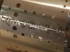
Anyways, I have included a couple of pictures of a few parts I made this weekend, the SS CC plates and NGV clamp rings. Both done by CNC.
Best Regards,
Haldor
Like the OP this is a long term project
A little history:
I have been active in RC for 30years, designing and building aircraft from scratch and my primary interest is gliders and DIY jets (EDF)
RBC kits in Holland still offer my design in kit form, a single motor EDF MiG29.
I am currently not active in RC as I fly fullsize gliders (own a LS6a) but I havent quit
Norwegian in Norway...
So now I am in the process of building my first turbine and I chose the GR130 due to apparent simple design, relative amount of updated information etc.
This thread is the only active build log so I signed in to this forum with the intention to interact
I have a CNC so making some of the parts are relative straight forward, I do not have a lathe (atleast not yet...) so the turned parts like the diffusor is on hold. I made on on the CNC but accuracy is not close enough yet. (its a DIY CNC)
Here is a video of the first diffusor being CNC'd :
Anyways, I have included a couple of pictures of a few parts I made this weekend, the SS CC plates and NGV clamp rings. Both done by CNC.
Best Regards,
Haldor
Bijlagen


Here is a couple more photos of parts I made earlier this year. These are not usable due to some production errors while learning CNC..
Currently I am not equipped to produce the turbine shaft or shaft holder, I might consider purchasing a set if there are a set available. If anyone do, drop me a line please
NGV/turbine wheel will also be purchased but that is further down the line
Currently I am not equipped to produce the turbine shaft or shaft holder, I might consider purchasing a set if there are a set available. If anyone do, drop me a line please
NGV/turbine wheel will also be purchased but that is further down the line
Bijlagen

BTW - the current compressor wheel I have (Garrett 409179-0018) is slightly different than the -0022 originally used for the GR130.
Intake diameter = 48.35mm vs 49,50mm and 5,9mm tip height vs 6.0mm = marginal differences. My primary goal is to get it running, maximizing performance will be stage two...
My next job will be to spot weld the combustion chamber as soon as I have fabricated the front/rear plate the walls mount to.
Intake diameter = 48.35mm vs 49,50mm and 5,9mm tip height vs 6.0mm = marginal differences. My primary goal is to get it running, maximizing performance will be stage two...
My next job will be to spot weld the combustion chamber as soon as I have fabricated the front/rear plate the walls mount to.
Nice work Haldor, curious on your progress! Please bear in mind that I don't have any data on this engines current compressor versus diffuser match yet as it was drawn experimental based on other projects. Also your compressor will be on experimental basis but I don't expect any large significant changes, maybe very slight decrease in pressure and thrust. Please post results
Kind regards,
Gerald
Kind regards,
Gerald
Hi Gerald and thanks for posting
I share for fun but also to seek guidance as this is new territory for me, turbine and metal work") 2years ago I didnt even know how to build or operate a CNC
2years ago I didnt even know how to build or operate a CNC  but now I know..more
Regarding the compressor I dont expect much difference, atleast not in a will work/wont work difference so not concerned there. If the turbine wont work it will not be due to the compressor alone.
The diffusor only need to be a smidge lower to accomodate the narrower gap and the intake bell need a change in ID/radius.
Spot welded the inner chamber last nite, which was a first. Did okay.. 12V battery and copper piping to the rescue
Question:
Spot welding or brazing, is brazing adequate in terms of temps of the CC walls?
I share for fun but also to seek guidance as this is new territory for me, turbine and metal work
2years ago I didnt even know how to build or operate a CNC but now I know..more Regarding the compressor I dont expect much difference, atleast not in a will work/wont work difference so not concerned there. If the turbine wont work it will not be due to the compressor alone.
The diffusor only need to be a smidge lower to accomodate the narrower gap and the intake bell need a change in ID/radius.
Spot welded the inner chamber last nite, which was a first. Did okay.. 12V battery and copper piping to the rescue
Question:
Spot welding or brazing, is brazing adequate in terms of temps of the CC walls?

aluminum is no problem
After waiting for a new tungsten carbide end mill I was finally able to cut out the front/rear CC walls.
Turned the front wall flanges down by hand using two stacked layers of 19mm MDF rings with the steel plate sandwiched in-between. The MDF rings were CNC´d to correct dimension and I used blue masking tape / CA to bond the steel plate centred between the two.
Using a hammer and going slowly/light I was able to achieve a nice flange Repeated for the inside but since the hole is only about 42mm wide there isn't much room for hammering
So I used a round bar as a rolling pin and slowly the right opening diameter was achieved.
This is my first attempt at metalworking so quite pleased with the outcome
As I dont have a NGV on hand I will CNC a disk blank I can use as guide when spot welding the inner CC tube exit side to exact diameter.
...slow and steady...


Turned the front wall flanges down by hand using two stacked layers of 19mm MDF rings with the steel plate sandwiched in-between. The MDF rings were CNC´d to correct dimension and I used blue masking tape / CA to bond the steel plate centred between the two.
Using a hammer and going slowly/light I was able to achieve a nice flange
Repeated for the inside but since the hole is only about 42mm wide there isn't much room for hammering So I used a round bar as a rolling pin and slowly the right opening diameter was achieved.
This is my first attempt at metalworking so quite pleased with the outcome
As I dont have a NGV on hand I will CNC a disk blank I can use as guide when spot welding the inner CC tube exit side to exact diameter.
...slow and steady...
Current status:
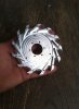
Machined a new diffusor as the first one have machining errors and serve no purpose other than "being first"
Diffusor mk2 has a diameter of 105mm which fit the actual CV470 canister I got very well.
Hopefully I can machine the outer diffusor cover over the weekend
The new diffusor is carved only on the front side so far, will do the rear side later.
2mm guide holes are machined 3mm deep and will be drilled to 2,4mm diameter once the outer cover is done. That way I can hopefully achieve a precise and centered fit.
Bijlagen


Looking good Haldor!
Minor update, the diff.cover have been matched to the diffusor and all the M3´s holes have been threaded
Also the canister have been fitted so now it start to look like an engine! Over the holidays I will continue with the inlet bell and the CC/fuel tubes.
Also the canister have been fitted so now it start to look like an engine! Over the holidays I will continue with the inlet bell and the CC/fuel tubes.
Bijlagen

Wife is out of town (kids are not) so I didn't get to spend a lot of time with the CNC today so opted to begin some of the more tedious tasks like opening the rear end of the canister and starting the fuel delivery system.
First the brass 6mm and 3mm rods were annealed and formed quite nicely to a decent shape. I will braze these during work hours the coming week hopefully. I also found a cup from an old thermos bottle with OD70mm which neck down to 48mm, perfect exhaust cone

First the brass 6mm and 3mm rods were annealed and formed quite nicely to a decent shape. I will braze these during work hours the coming week hopefully. I also found a cup from an old thermos bottle with OD70mm which neck down to 48mm, perfect exhaust cone
Bijlagen


Tadango
Forum veteraan
Question regarding the brass tubes running through the diffusor/front cover:
These need to be sealed, how would the best way to achieve that be, press fit?
What i see is a o ring between the intake cover and the diffusor. When you screw on the intake cover the o ring is pressed against the brass tube. A small space for the o ring is created in the intake cover. For a first test a good fit is enough.
Thank you for the reply Tadango
O-ring or some kind of sealant between the diffusor and diff.cover it is then
Speaking of sealing and alu / steel expansion rates:
My diff.cover sit veeeeery tight onto the CV470 canister, I must "hammer" it in place and use force to disassemble. Alu expand more than steel so maybe I should make it less tight and use the proposed O-ring seal here aswell?
Progress will be slow the next couple of weeks due to the holidays etc but I'll keep at it